

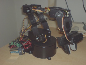
This document is based on the LynxMotion AL5A manipulator arm, plus the lightweight wrist-rotate extension. This is the smallest arm that LynxMotion provide, and was chosen as it represents the cheapest entry into a fascinating hobby, you can do all the experimental stuff that you could with a bigger arm, and it is also a bit more stable than a bigger arm due to smaller leverage action. The arm is composed of aluminium brackets pivoted together. The axes of all the pivots are very physically the axes of the output shafts of the electric motors, which not only drive the arm but provide much of the strength of the construction; these are completely sealed units housing the motor, gearbox, position feedback sensor and control electronics. While the built-in electronics use dynamic position feedback to control the motor positioning, it is not possible to return this position information back to the controlling PC via the serial cable; nor is it possible to get a measure of the effort which the motors expend in carrying out manoeuvres.
In very many ways the robot design is an ideal mix of hardware and software. The hardware is such that, whatever you try to do to it either through software control or manually, you will not break the device (within reason, of course). The firmware relieves the software of the very fine details and signal timings required to drive the motors directly, but leaves a relatively low-level interface that the software can use to access all aspects of robot control. (There are also programs in the firmware which provide higher-level support for moving multiple axes, and for operating a hexapod robot, but we are not interested in them.) However, this alone is not enough to properly deploy the arm; software is required to make the arm do useful work, and the software provides the flexibility to apply the arm to any task within its capability envelope. The perfect marriage!
An interesting aspect of this construction is that all the motors turn through exactly the same angles for given changes in input, and as you move along the power chain from the base to the gripper at the end of the arm, the motors are alternately mounted in opposite senses. This means that if, for example, the shoulder and elbow are both moved by 200 microsteps (uS), then they will move in opposite directions leaving the orientation of the forearm completely unadjusted — in other words, the forearm will always be parallel to its original orientation. This has two benefits: it is easier to understand how the gripper will move during such a manoeuvre making silly mistakes (crashing the arm into itself) less likely, and the two motors work in each others favour — the elbow relieves some of the stress of the movement from the shoulder.
If you are contemplating coming into this exciting new hobby, you are probably thinking that it merely involves screwing together a bit of Mechanno, plugging it into the mains, connecting to a PC, and whoopee! Well, while that sums up the process, you will find far more subtleties along the way than you could have imagined at the start. The purpose of this section is to give an overview of these, and then the rest of the document works out the resolution of all the issues to leave a robot that really comes to life!
It is fair to say that when you do eventually first apply a signal to a powered robot arm, it will jump (quite ferociously!) into action. However, a robot only really comes alive when all the motors are working simultaneously and in harmony, with smoothly accelerated and braked movements which work together to get a task completed with maximal efficiency. Working in this way will not only produce a more aesthetically pleasing robot, but will see jobs done quicker in the long run, and will keep the robot running reliably for longer.